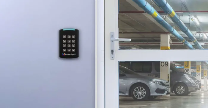
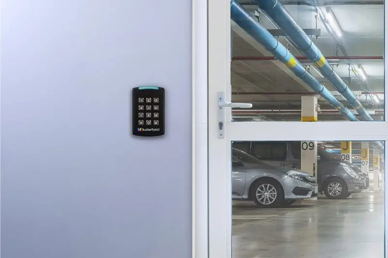
ButterflyMX’s cloud-based readers pair effortlessly with the 2-door controller to empower your customers to easily operate and manage doors and gates using their smartphone, fob, keycard, or PIN code. The readers come in two variations – the smaller, fob-reading mullion reader and the larger, PIN-code-activated keypad. These solutions seamlessly integrate with their video intercom, elevator controls, and smart locks, offering a unified smartphone-based access solution.
Read this post to continue the ButterflyMX access control installation process and install your client’s readers.
Follow these instructions to install the ButterflyMX readers:
Mount the reader
To begin the installation process of the ButterflyMX readers, start by securely mounting the reader to the wall.
How to mount the reader:
Step 1: Install the reader’s wall plate
Install the metal wall plate to the gang box using the provided #6 screws.
Step 2: Attach the reader to the wall plate
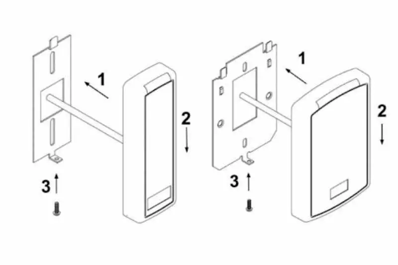
Align the reader so that the tabs of the base plate slide into the slots on the wall plate. Then, move the reader into position.
Step 3: Install the reader screw
Install the #4-40 screw or pin-in-torx at the bottom of the reader.
Join ButterflyMX’s industry-leader dealer program:
Connect the reader
Next, connect the reader to the 2-door controller.
Important note: Always disconnect power from the 2-door access controller and locking hardware when wiring readers and other devices. Failure to do so can damage the controller and any connected accessories.
Follow these three steps to connect the ButterflyMX reader to the 2-door controller:
Step 1: Prep the reader
Before connecting the reader, secure all of the unused wires using electrical tape to ensure none of the exposed wires are touching. This includes the brown, yellow, blue, and orange wires on the pigtail. Then, run the reader cable through the hole on the mounting plate and connect the reader to the controller
Step 2: Connect the reader to the controller
Next, connect the reader to the 2-door controller by following these instructions:
- Confirm all colors on the reader pigtail correspond to the correct colors on the reader port.
- Connect the reader to the controller by splicing the black, white, green, and red wires on the reader pigtail to the reader cable.
- Using the CAT Cables (double up wires for GND and 12V), splice one twisted pair (two wires) to GND and another twisted pair to 12V and splice a singular wire to D-/L- and the other singular wire (of that same pair) to D+/L+. There will be one pair that is left unused.
- Last, with all other cables (non-CAT cables), splice singular wires to GND, D-/L-, D+/L+, and 12V then connect the reader cable to the controller, making sure the reader pigtails are connected to the correct termination.
Step 3: Test the reader’s connection
To test the connection from the reader to the controller, enter the zip code of the building where the reader is being installed, followed by the pound sign (e.g. 10001#). If the connection is functional, both the reader and the controller will display a green light.
For more information on installing ButterflyMX readers, visit the installer resources page on our website.