If you’re installing a ButterflyMX video intercom at a property that does not have an access control system, you can wire the intercom straight to a Direct Current (DC) powered lock. Doing so will require electrical isolation to protect the intercom from the inductive kickback. Follow the instructions in this post to prepare an isolation relay DC strike integration.
To connect to a DC strike, you’ll need:
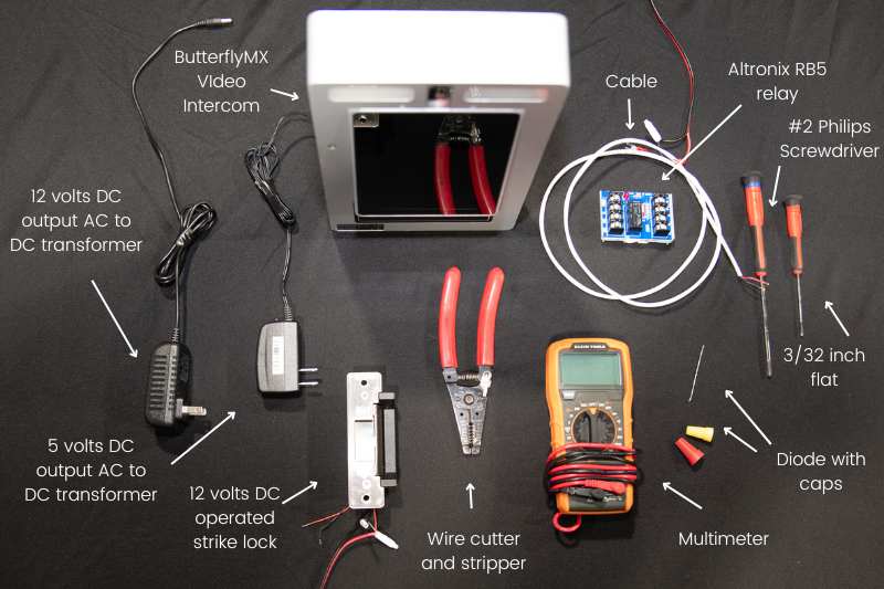
- ButterflyMX video intercom
- 5 volts DC output AC to DC transformer
- 12 volts DC output AC to DC transformer
- 12 volts DC operated strike block
- A multimeter
- Altronix RB5 relay (set to 6 volt DC operation)
- A diode (minimum 400v, 1amp, 1N4004 type) with caps/dolphins
- 3/32 inch flat
- #2 Phillips screwdriver
- Wirecutter and stripper
- Cable
How to connect to a DC strike:
- Check the polarity of the two power sources
- Properly prepare the conducting wires used
- Terminate the connections into the relay
- Show the ButterflyMX video intercom operating the relay
- Terminate the connections in the strike lock from the power source
- Operate the entire system from activation in the ButterflyMX video intercom
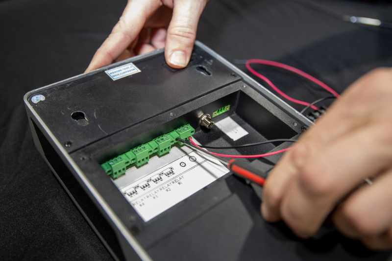
Step 1: Check the polarity of the two power sources
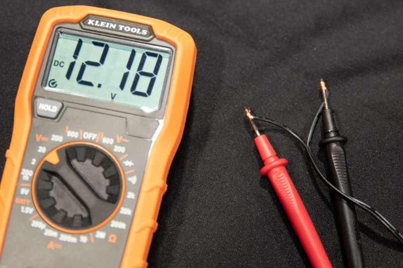
Make sure the power sources are not plugged in and begin with the 5-volt source. First, separate the two conductor wires, the positive wire is suspected to be unmarked and the negative is suspected to be marked. Strip enough of each conductor’s insulation to have adequate wire for a firm and stable connection to the multimeter. Then, wrap each wire into the multimeter’s probes, the suspected positive to red and the suspected negative to black.
Test the multimeter function by setting it to the correct 5-volt DC voltage setting, it should read 0 volts. Then, proceed to energize the circuit. The multimeter should read around 5 volts, with the correct polarity as it displays a positive number.
Step 2: Properly prepare the conducting wires used
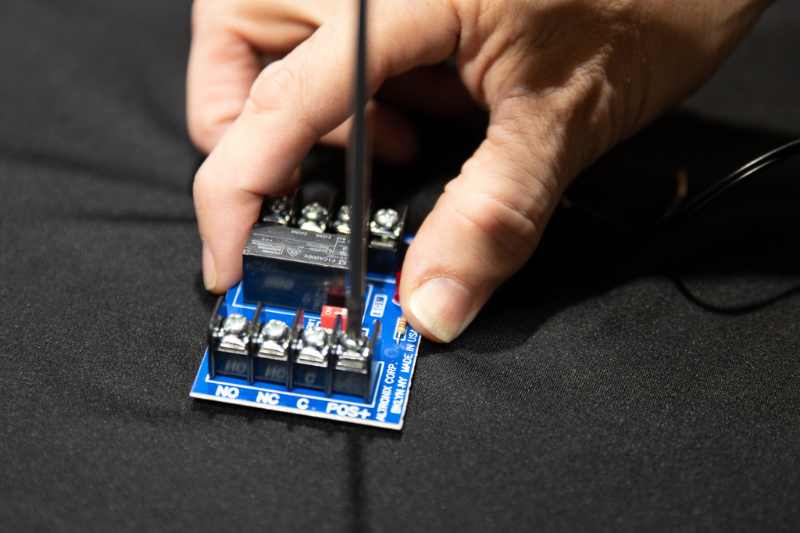
With the polarity of the power sources verified, you’ll now connect the ButterflyMX intercom to the relay and circuit power source. First, properly strip the positive conductor of the 5-volt DC adaptor to fit the terminal labeled “POS+” in the RB5 unit. Open this terminal using a #2 screwdriver. Then, insert the positive conductor into the terminal labeled “POS+” into the RB5 unit and screw it in securely, making sure the conductor has good contact and has no excess wire that could cause a short.
Repeat the stripping process with the negative conductor. But this time, insert it into the ButterflyMX dry relay common terminal.
Step 3: Terminate the connections into the relay
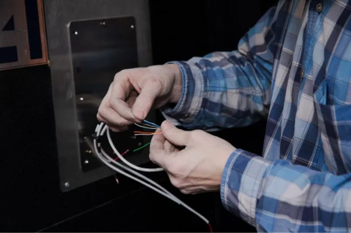
Next, prepare the conductor for the connection from the ButterflyMX intercom’s normally open port to the RB5 relay. You’ll need to strip away the insulation and cut off the rest of the wires in the cable. If desired, you can also twist them into the insulation. Do this on both ends, retaining only the wire of the chosen color. Carefully insert the conductor into the port, ensuring that it goes in correctly and there are no stray strands of wire. Also, ensure there are no wires, or very little wire visible. Then, proceed to insert the termination block into the ButterflyMX intercom, you’ll screw this in with a 3/32 screwdriver. Ensure the connection is secured correctly.
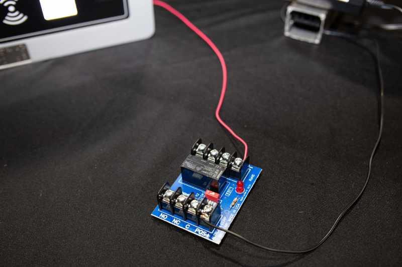
Step 4: Show the ButterflyMX video intercom operating the relay
Next, energize the circuit. With it properly energized, proceed to activate the normally open relay in the ButterflyMX intercom. The LED indicator light will turn on, showing the relay is properly being activated.
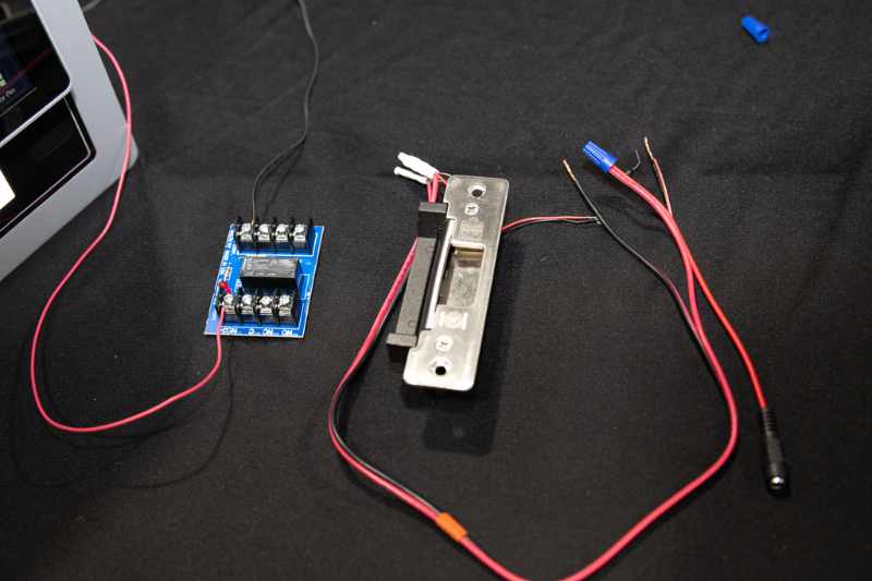
Step 5: Terminate the connections in the strike lock from the power source
Prepare the conductor for the connection from the strike lock’s negative conductor to the RB5’s relay normally open port. The diode has a polarity, and the marked side goes with the positive. When using caps, it’s not necessary to twist the wires together as the twisting motion of the cap is enough to ensure a safe and secure connection. You’ll then complete the other conductor.
Next, verify that the connection is safely and firmly secured. Also, verify that both conductors that connect to the RB5 are ready to be terminated. Beginning with the conductor from the power adaptor, we verify again that it’s ready. Using a #2 Phillips screwdriver, open the common terminal on the relay “NEG-” side. Insert the conductor into the terminal then close the terminal using the #2 Phillips screwdriver.
Repeat the process with the conductor from the strike that goes into the normally open terminal. Verify that both conductors are safely and securely connected.
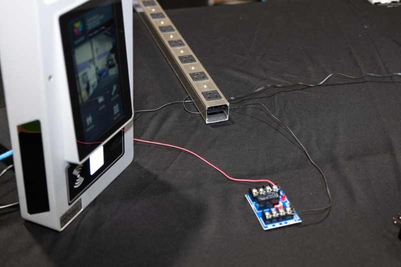
Step 6: Operate the entire system from activation in the ButterflyMX video intercom
Now, energize the circuit then activate the ButterflyMX intercom. The strike lock will open and the indicator LED in the RB5 relay will light up showing the ButterflyMX intercom has activated.
And that’s how you prepare an isolation relay DC strike integration. To learn more about installing ButterflyMX products, check out our installer resources.